


After understanding the hardware of the Arduino UNO board in the previous article, let's now get started with Arduino programming.
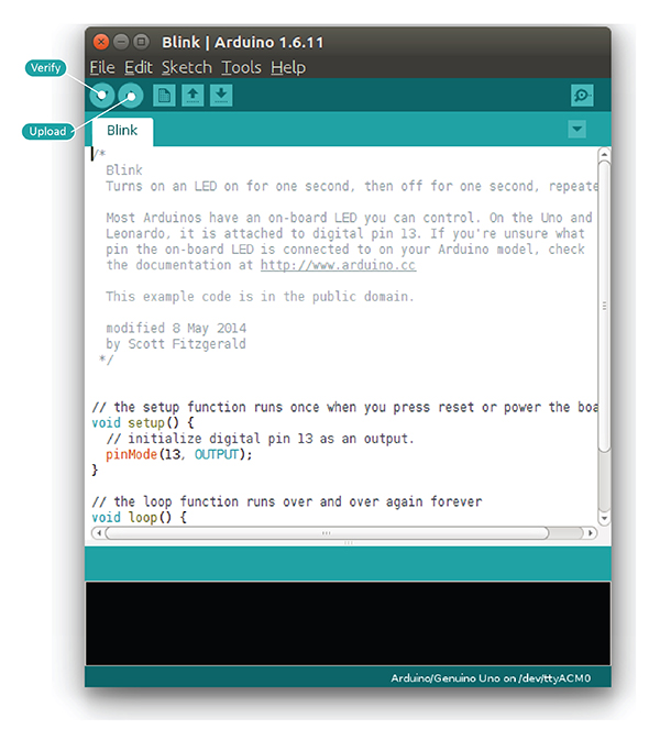
Arduino programs are written in the Arduino Integrated Development Environment (IDE). Arduino IDE is a special software that allows you to write sketches (programs) for different Arduino boards. The Arduino programming language is based on a simple hardware programming language called Processing, which is similar to the C language. After writing a sketch in the Arduino IDE, it should be uploaded to the Arduino board for execution.
The first step in programming the Arduino board is downloading and installing the Arduino IDE. It runs on Windows, Mac OS X, and Linux. Download the software from the official website and follow the installation instructions.
Now let’s discuss the basics of Arduino programming.
The structure of an Arduino program includes two main blocks:
- Preparation
- Execution
void setup() {
  // initialization statements
}

void loop() {
  // execution statements
}
The setup() function runs once when the program starts. It’s used to initialize pin modes and start serial communication. Even if there are no statements, the function must be included.
void setup() {
  pinMode(pin-number, OUTPUT); // set pin as output
  pinMode(pin-number, INPUT);  // set pin as input
}
After setup(), the loop() function runs repeatedly and contains the main program logic.
void loop() {
  digitalWrite(pin-number, HIGH); // turn ON
  delay(1000); // wait 1 second
  digitalWrite(pin-number, LOW);  // turn OFF
  delay(1000); // wait 1 second
}
Note: Arduino measures time in milliseconds.
Let’s Try Two Experiments
- Blinking the LED
- Fade-in and fade-out the LED
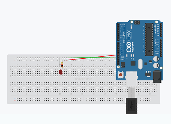
Building the breadboard circuit is just as important as writing the Arduino code.
Components Required:
- Arduino UNO R3 - 1
- Breadboard - 1
- Breadboard connectors - 3
- LED - 1
- 1K resistor - 1
Blinking LED
Steps:
- Connect the Arduino to your computer via USB.
- Connect digital pin 13 to the positive rail of the breadboard; GND to the negative.
- Connect the positive rail to a terminal strip through a 1K resistor.
- Fix the LED below the resistor on the strip.
- Connect the LED's cathode to the negative rail.
Code Version-1:
int LED = 13;

void setup() {
  pinMode(LED, OUTPUT);
}

void loop() {
  digitalWrite(LED, HIGH);
  delay(1000);
  digitalWrite(LED, LOW);
  delay(1000);
}
Code Version-2:
void setup() {
  pinMode(13, OUTPUT);
}

void loop() {
  digitalWrite(13, HIGH);
  delay(1000);
  digitalWrite(13, LOW);
}
Fade-in and Fade-out the LED
Note: Use digital pin 9 instead of 13 in the above circuit.

Code Version-1:
int led = 9;
int brightness = 0;
int fade = 5;

void setup() {
  pinMode(led, OUTPUT);
}

void loop() {
  analogWrite(led, brightness);
  brightness = brightness + fade;

  if (brightness <= 0 || brightness >= 255) {
    fade = -fade;
  }

  delay(30);
}
Code Version-2:
int led = 9;

void setup() {
  pinMode(led, OUTPUT);
}

void loop() {
  for (int fade = 0; fade <= 255; fade += 5) {
    analogWrite(led, fade);
    delay(30);
  }
}
Both programs use analogWrite() on a PWM-capable digital pin. PWM pins simulate analog output.
Congrats! You’ve completed level-1 of Arduino programming. In level-2, you’ll explore conditional statements, loops, and I/O operations. Continue learning here.


